Creating a Circuit in Unity
In Elevator Circuit, the objective is to complete a circuit by moving elevators holding circuit segments, aligning them into a complete path. It currently has five short puzzles with more to come. My biggest role in the project was to program the circuit system.

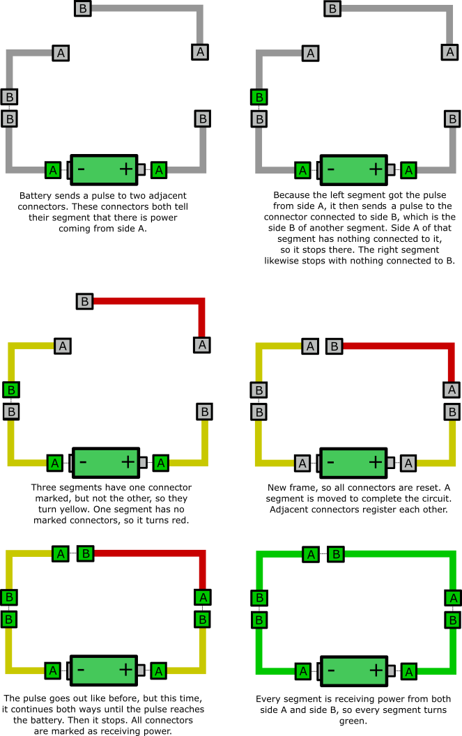
The idea was that any segment without a path to a generator would be red. A segment with a path from one side, but not a path from the other is yellow. When there is a path to a battery from both sides, current can actually pass through the segment, it turns green. I used Procedural Lightning to indicate that the connectors of two segments are close enough to be connected (It happens even when the two segments are not connected to a battery, but we needed some kind of feedback).
Completing circuits is an element of many puzzle games, so I figured sharing this experience could be helpful to others.
My first (failed) attempt
I made a script for each connector that checked for other connectors to enter and exit its trigger area. It then registered the segment of the other connector to current segment. The connector then told the segment to update its material by recursively checking its neighboring segments, and then its neighbor’s neighbors, until it either dead-ends, loops , or reaches a battery. All the segments along that path would update their materials accordingly. I soon ran into all sorts of race conditions and edge cases. The lightning would correctly connect segments, but the colors of the segments would be wrong half the time. So, I scrapped that and tried something new.
Pulsing from the battery
Since there would only ever be a handful of segments in any stage, it would not be too expensive to check for changes every frame. I kept what I had before with each connector registering other segments to its own segments, but instead of updating the materials only during a connection change, the battery would “pulse” every frame. Going recursively to each connected segment from the battery, it would mark the visited segments as “connected” either from the left or right, depending on where the pulse came from. The segments would then all update their materials accordingly, the frame would render, and then the connections would reset for the next pulse.
If you want circuits in your own project, download the code. Extract it, and add the two c# scripts to your project. I recommend checking the code out for yourself. I added lots of comments. There are two scripts:
- CircuitConnector.cs: This gets attached to the individual connectors, labeled A and B in the diagram, although in the code, I refer to "left" and "right". They must handle collisions with other connectors to register connections, so each connector object will need this script, a rigidbody for collisions (it can be kinematic), and a trigger collider for its range for connection.
- CircuitSegment.cs: This gets attached to the entire segment object. Normally this would be the parent of the connectors, although it technically does not have to be with how I set up the code. Add the segment to both connectors through the inspector, and then mark one of them as left (it doesn't matter which one). You will also need to assign to the segments the materials you want to paint onto the wires. Any children of the segment with the tag "Wire" will be painted those materials, so be sure to set up that tag.
Mark any segment as having a battery in the inspector, and that segment will now supply power and initiate the pulses. Now, if you have some object you want a complete circuit to trigger, like opening and closing a door, make a new script with two public methods such as Open() and Close(). On the segment that powers the object, you can assign those methods in the inspector through the Power Event and Lose Power Event.
Leave a comment
Log in with itch.io to leave a comment.